Observation: everyone creates their version [of motor controller/driver board]
or relies on currently available shields or hats
- Pimoroni Yukon board
Photo by Dr Footleg Yukon driver board](/static/38cf2d27fadc3ce5a708235b6cf9f10b/6aca1/pimoroni_yukon.jpg)
Maybe that's why Yukon is very popular, but why not to make this customly expandable?
H-Bridge
H-bridge, also called as full bridge (but not half bridge), is a motor driver that allows the motor to rotate forward and backward. With independent movement of every wheel we will implement skid-steer drive. H-Bridge can be created with the help of four MOSFETs and diodes.
Unwise to power an H-bridge with two d-a's, forward and reverse, you run risk of powering both sides on at once. This destroys the H-bridge and can destroy the motor. Be really careful. You can only power one at a time.
Tony about homemade H-Bridge implementation
Or it can be an IC. I looked into this breakout board based on classic TB6612 that supports 2 motors and 1.2A per channel. Other super classic options will be L293D and L298.
So why not to use classic bridges like L298N, or L293D, or TB6612? Because they cost $12 per chip, and they are out of stock 😭
Next, I check what chips are available at the moment. Texas Instruments offers
I had a gut feeling that I didn’t check all specs for my H-Bridges. I stopped my choice on
- DRV8836 Dual Low-Voltage H-Bridge IC from Texas Instruments and
- A3909 Dual Full Bridge Motor Driver from Allegro Microsystems
I was checking level input voltage, how many motors it can drive (checking the type of connection that is different for DC motor, bipolar DC motor, and stepper motor), and was comparing stall motor current with maximum output current.
Speed control
First I started worrying what kind of input is required. UART, I2C protocol, PWM signal? How to implement speed control? Do I need Digital-to-analog converter?
My friend Tony asked his engineer the same questions and he raised many questions about the design, ADC and precautions against H-Bridge.
Let's think. It’s not a stepper motor, therefore we don’t need to send pulses, just ON or OFF signals. PWM might produce different speed. I need to check how many PWM outputs on ATMega chips. But the question is: is it possible to simulate PWM on regular DOUT?
Dual channel
Guess how I was surprised today that Dual Full Bridge means that the second motor is moving exactly as the first one. And we are talking about bipolar DC motors. Yes, it’s not another independent channel. IT IS NOT.
Looking at TI's DRV8210 and Toshiba's TC78H660FTG now 😋 Another alternative can be TMC7300 that includes DC converter and can work from the battery directly.
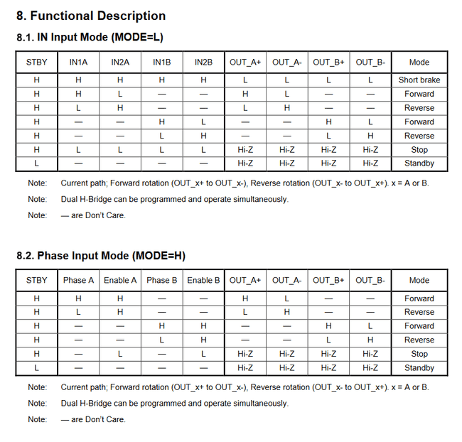
How to verify it? Datasheets should include a control table - output levels corresponding to input signals. Here's for example A3909 that disappointed me (DC Motor section, INs are merged - not independent)
For DRV8836 we will see completely different picture. There one small table that works for both channels (1 and 2) and marked as 'x'
And compare both previous tables with this clear table and extra notes from Toshiba TC78H660FTG 😍
Schematics
Full-Bridge driving typical application
PWM interface motor-driving application for DSG package
Note: Pay attention to a paragraph about bulk resistance
Additional components:
- 1x capacitors 10uF - voltage Rating 6.3VDC
Alternative boards
- Adafruit CRICKIT
- ROSRider
- Adafruit TB6612 1.2A DC/Stepper Motor Driver Breakout Board (TB6612)
- A-Star 32U4 Robot Controller LV with Raspberry Pi Bridge (DRV8838). Using their schematics I verified that there is no need to add more capacitors or resistors to the original scheme.
- X-NUCLEO-IHM08M1 (L6398). Half bridge, but oriented on brushless motors that require a special algorithm to supply power, which is a part of hardware.
- MAX22007 Peripheral module `
- Driver for stepper motors
- PCA9685 which is actually 16-channel PWM LED controller used in Pi Servo Hat
Questions
Q I plan to do 4 motors. A chip per motor or dual channel ICs? What if I do more motors? 🤔
A ...
Q Software PWM VS Hardware PWM


